Modbus Address Mapping Demystified: Register Ranges, Function Codes, and Sorted-Tag Optimization [2026]
If you've ever stared at a PLC register map and wondered why address 400001 is actually register 0, or why your gateway reads the wrong data when you mix holding registers with input registers in the same request — this article is for you.
Modbus addressing is one of the most misunderstood aspects of industrial communication. The protocol itself is simple. The addressing conventions built on top of it are where engineers lose hours to debugging. And the optimization strategies for reading registers efficiently can cut your polling time in half.
Let's break it all down.

The Four Register Ranges
Modbus defines four distinct data spaces, each with its own addressing convention and access characteristics:
| Range | Address Convention | Function Code (Read) | Function Code (Write) | Data Type | Access |
|---|---|---|---|---|---|
| Coils | 0xxxxx (0–65535) | FC 01 | FC 05/15 | Single bit | Read/Write |
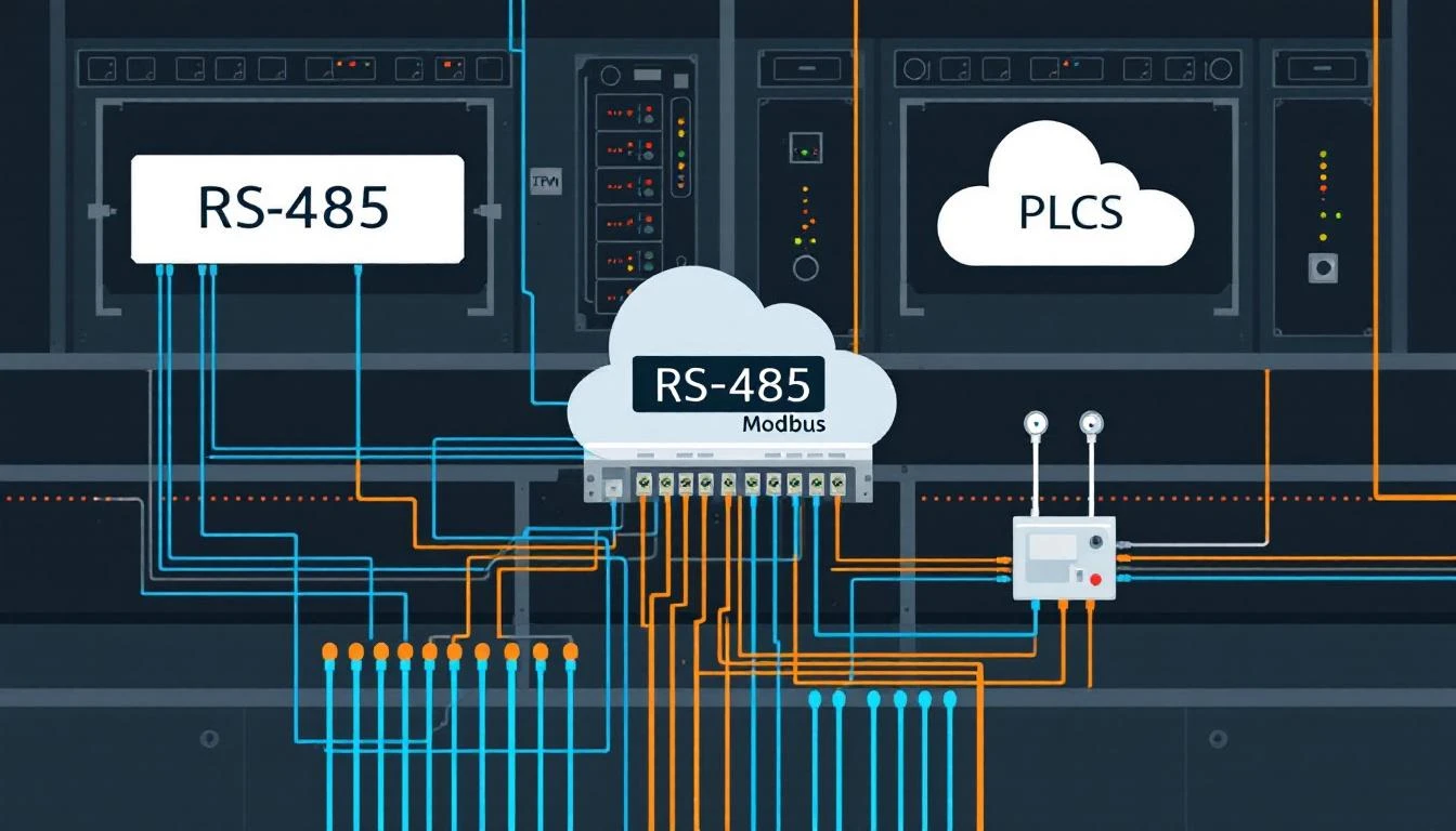
| Discrete Inputs | 1xxxxx (100000–165535) | FC 02 | — | Single bit | Read Only |
| Input Registers | 3xxxxx (300000–365535) | FC 04 | — | 16-bit word | Read Only |
| Holding Registers | 4xxxxx (400000–465535) | FC 03 | FC 06/16 | 16-bit word | Read/Write |
The Great Addressing Confusion
Here's the source of 90% of Modbus debugging pain: the convention addresses include a prefix digit that doesn't exist in the actual protocol.
When you see "address 400001" in a PLC manual, the actual register address sent over the wire is 0 (zero). The "4" prefix tells you it's a holding register (use FC 03), and the remaining digits are 1-indexed, so you subtract 1.
Convention Address → Wire Address
400001 → Holding Register 0 (FC 03)
400100 → Holding Register 99 (FC 03)
300001 → Input Register 0 (FC 04)
000001 → Coil 0 (FC 01)
100001 → Discrete Input 0 (FC 02)
Some PLC manufacturers use 0-indexed conventions (Modicon style), while others use 1-indexed (common in building automation). Always verify with the actual PLC documentation. Getting this wrong by one register means you're reading the wrong variable — which might look plausible but be subtly incorrect, leading to phantom issues that take days to diagnose.
Automatic Function Code Selection
A well-designed gateway should automatically determine the correct Modbus function code from the register address, eliminating manual configuration errors:
Address Range           → Function Code
0 – 65535              → FC 01 (Read Coils)
100000 – 165535        → FC 02 (Read Discrete Inputs)
300000 – 365535        → FC 04 (Read Input Registers)
400000 – 465535        → FC 03 (Read Holding Registers)
This means the engineer configuring the gateway only needs to specify the convention address from the PLC manual. The gateway strips the prefix, determines the function code, and calculates the wire address automatically.
To extract the wire address from the convention address:
if address >= 400000:
    wire_address = address - 400000
    function_code = 3
elif address >= 300000:
    wire_address = address - 300000
    function_code = 4
elif address >= 100000:
    wire_address = address - 100000
    function_code = 2
else:
    wire_address = address
    function_code = 1
16-Bit vs. 32-Bit Values: The Element Count Problem
Each Modbus register holds exactly 16 bits. But many real-world values are 32-bit (floats, unsigned integers, large counters). This requires reading two consecutive registers and combining them.
Element Count Configuration
When configuring a tag, you specify the element count — how many 16-bit registers to read for this tag:
| Data Type | Element Count | Registers Read |
|---|---|---|
bool | 1 | 1 register (only LSB used) |
int8 / uint8 | 1 | 1 register (masked to 8 bits) |
int16 / uint16 | 1 | 1 register |
int32 / uint32 | 2 | 2 consecutive registers |
float (IEEE 754) | 2 | 2 consecutive registers |
Byte Ordering (The Endianness Trap)
When combining two 16-bit registers into a 32-bit value, the byte order matters — and different PLCs use different conventions:
Big-endian (Modbus standard): Register N = high word, Register N+1 = low word
uint32_value = (register[N+1] << 16) | register[N]
Little-endian (some PLCs): Register N = low word, Register N+1 = high word
uint32_value = (register[N] << 16) | register[N+1]
For IEEE 754 floating-point values, the situation is even trickier. The modbus_get_float() function in libmodbus handles the byte swapping, but you need to know your PLC's byte order. Common byte orderings for 32-bit floats:
| Order | Name | Register Layout |
|---|---|---|
| ABCD | Big-endian | Most common in Modicon/Schneider |
| DCBA | Little-endian | Some Allen-Bradley |
| BADC | Mid-big-endian | Siemens S7 |
| CDAB | Mid-little-endian | Some Japanese PLCs |
Pro tip: If you're getting nonsensical float values (like 1.4e38 when you expect 72.5), you almost certainly have a byte-order mismatch. Swap the register order and try again.
Handling 8-Bit Values from 16-Bit Registers
When a PLC stores an 8-bit value (bool, int8, uint8) in a 16-bit register, the value sits in the lower byte:
register_value = 0x00FF  # Only lower 8 bits are the value
int8_value = register_value & 0xFF
bool_value = register_value & 0x01
This is straightforward for single registers, but gets interesting when you're reading coils (FC 01/02). Coil reads return packed bits — 8 coils per byte — which need to be unpacked into individual boolean values.
Sorted-Tag Optimization: Contiguous Register Grouping
This is where theory meets performance. A naive implementation reads each tag individually:
# Naive: 10 tags = 10 separate Modbus requests
read_register(400100)  # Temperature
read_register(400101)  # Pressure
read_register(400102)  # Flow rate
read_register(400103)  # Setpoint
...
Each Modbus request has overhead: a request frame (~8 bytes), a response frame (~8 bytes + data), and a round-trip delay (typically 5-50ms on a LAN, 50-400ms on serial). Ten individual reads means 10× the overhead.
The Contiguous Grouping Algorithm
Instead, a smart gateway sorts tags by address and groups contiguous registers into single multi-register reads:
# Optimized: 10 contiguous tags = 1 Modbus request
read_registers(400100, count=10)  # All 10 values in one shot
The algorithm works in four steps:
Step 1: Sort tags by address. When the configuration is loaded, tags are inserted into a sorted linked list ordered by their register address. This is critical — without sorting, you can't detect contiguous ranges.
Step 2: Identify contiguous groups. Walk the sorted list and group tags that satisfy ALL of these conditions:
- Same function code (same register type)
- Addresses are contiguous (tag N+1 starts where tag N ends)
- Same polling interval
- Total register count doesn't exceed the protocol limit
# Grouping logic
head = first_tag
registers = head.element_count
tags_in_group = 1

for each subsequent tag:
    if tag.function_code == head.function_code
       AND head.address + registers == tag.address
       AND head.interval == tag.interval
       AND registers < MAX_REGISTERS:
        # Attach to current group
        registers += tag.element_count
        tags_in_group += 1
    else:
        # Read current group, start new one
        read_registers(head.address, registers)
        head = tag
        registers = tag.element_count
        tags_in_group = 1
Step 3: Respect the maximum register limit. The Modbus spec allows up to 125 registers per read request (FC 03/04) or 2000 coils per read (FC 01/02). In practice, many PLCs have lower limits. A safe ceiling is 50 registers per request — this keeps response sizes under 100 bytes, reducing the chance of packet fragmentation and timeouts.
Step 4: Dispatch values. After the multi-register read returns, walk the buffer and dispatch values to individual tags based on their position in the group.
Performance Impact
On a typical Modbus TCP network with 5ms round-trip time:
| Tags | Naive Approach | Grouped Approach | Speedup |
|---|---|---|---|
| 10 | 50ms | 5ms | 10× |
| 50 | 250ms | 25ms (5 groups) | 10× |
| 100 | 500ms | 50ms (10 groups) | 10× |
On Modbus RTU at 9600 baud, the difference is even more dramatic:
| Tags | Naive | Grouped | Speedup |
|---|---|---|---|
| 10 | 800ms | 120ms | 6.7× |
| 50 | 4000ms | 600ms | 6.7× |
For a gateway polling 50 tags every second, naive reads won't even fit in the time budget on serial. Grouping makes it feasible.
Handling Gaps
What about non-contiguous registers? If tags at addresses 400100 and 400105 need reading, you have two choices:
- Read the gap: Request registers 400100–400105 (6 registers), discard the 4 unused ones. Wastes bandwidth but saves a round-trip.
- Split into two reads: Two separate requests for 400100 (1 reg) and 400105 (1 reg). Two round-trips but no wasted data.
The breakeven point depends on your network. For gaps of 3 registers or fewer, reading the gap is usually faster. For larger gaps, split. A good heuristic:
if gap_size <= 3:
    read_through_gap()
else:
    split_into_separate_reads()
Inter-Read Delays: The 50ms Rule
After each contiguous group read, insert a small delay (typically 50ms) before the next read. This serves two purposes:
- PLC processing time: Some PLCs need time between successive requests to maintain their scan cycle. Hammering them with back-to-back reads can cause watchdog timeouts.
- Serial line recovery: On RS-485, the bus needs time to switch direction between request and response. Without this gap, you risk frame collisions on noisy lines.
read_group_1()
sleep(50ms)  # Let the PLC breathe
read_group_2()
sleep(50ms)
read_group_3()
This 50ms penalty per group is why minimizing the number of groups (through contiguous addressing) matters so much.
Change Detection: Read vs. Deliver
Reading a tag and delivering its value to the cloud are two separate decisions. Efficient gateways implement change detection to avoid delivering unchanged values:
if tag.compare_enabled:
    if new_value == tag.last_value:
        # Value unchanged — don't deliver
        update_read_timestamp()
        continue
    else:
        # Value changed — deliver and update
        deliver(tag, new_value)
        tag.last_value = new_value
Combined with interval-based polling, this creates a two-tier optimization:
- Interval: Don't read the tag if less than N seconds have elapsed since the last read
- Comparison: Don't deliver the value if it hasn't changed since the last delivery
The result: your MQTT bandwidth is dominated by actual state changes, not redundant repetitions of the same value.
Practical Configuration Example
Here's how a well-configured Modbus device might look in JSON:
{
  "protocol": "modbus-tcp",
  "device_type": 1017,
  "plctags": [
    {
      "name": "mold_temp_actual",
      "id": 1,
      "type": "float",
      "addr": 400100,
      "ecount": 2,
      "interval": 5,
      "compare": true
    },
    {
      "name": "mold_temp_setpoint",
      "id": 2,
      "type": "float",
      "addr": 400102,
      "ecount": 2,
      "interval": 60,
      "compare": true
    },
    {
      "name": "pump_running",
      "id": 3,
      "type": "bool",
      "addr": 000010,
      "ecount": 1,
      "interval": 1,
      "compare": true,
      "do_not_batch": true
    },
    {
      "name": "alarm_word",
      "id": 4,
      "type": "uint16",
      "addr": 400200,
      "ecount": 1,
      "interval": 1,
      "compare": true,
      "do_not_batch": true
    }
  ]
}
Notice:
- The two temperature tags (400100, 400102) are contiguous and will be read as one 4-register block
- They have different intervals (5s vs 60s), so they'll only group when both are due
- The alarm word uses
do_not_batch: true— it's delivered immediately on change, not held for the next batch - The pump running tag reads a coil (address < 100000), so it uses FC 01 — it can't group with the holding registers
How machineCDN Optimizes Modbus Polling
machineCDN's edge daemon automatically sorts tags by address at configuration load time, groups contiguous registers with matching intervals and function codes, and caps each read at 50 registers to prevent timeouts on older PLCs. The firmware handles the address-to-function-code mapping transparently — engineers configure tags using the convention addresses from the PLC manual, and the gateway handles the rest.
For devices with mixed protocols (e.g., a machine with EtherNet/IP on the main PLC and Modbus RTU on the temperature controller), machineCDN runs independent polling loops per protocol, each with its own connection management and buffering — so a failure on the serial line doesn't affect the EtherNet/IP connection.
Conclusion
Modbus addressing doesn't have to be painful. The key takeaways:
- Understand the four address ranges and how they map to function codes — this eliminates the #1 source of configuration errors
- Sort tags by address at configuration time to enable contiguous grouping
- Group contiguous registers into single multi-register reads — the performance improvement is 5–10× on typical deployments
- Handle 32-bit values carefully — element count and byte ordering are the two most common float-reading bugs
- Cap register counts at 50 per read to stay within PLC capabilities
- Use change detection to minimize cloud bandwidth — only deliver values that actually changed
- Insert 50ms delays between group reads to respect PLC processing requirements
Master these patterns, and you'll spend your time analyzing production data instead of debugging communication failures.